
vapour recovery system ppt
Recommend Products
PPT ENHANCED VAPOR RECOVERY PowerPoint presentation
PPT ENHANCED VAPOR RECOVERY PowerPoint presentation free to download id: 4204eb OTNmN. The Adobe Flash plugin is needed to view this content. Get the plugin now
Presentation of Vapour Recovery Systems M.P. Engg
→Determination of the pressure drop of the VRU and the vapour collecting system →Determination of the lines size, carbon bed diameter All vapours have to pass through the VRU.
Flash Vapour Calculation Flash Vapour Recovery Vessel
Condensate flash vapour recovery system calculation with example. What is Flash Vapour:. The liquid suddenly passing from high pressure to low pressure condition then produces a spontaneous evaporation without any external heat energy it is called “flash” or flash vapour.
Vapour recovery at service stations
Why we need vapour recovery at service stations. The petrol vapours from vehicles and service stations are a big contributor to poor air quality in NSW. Petrol vapours contain Volatile Organic Compounds (VOCs) including benzene, xylene and toluene.
1. Need for Tanker Vapor Recovery JFE Eng
9High Recovery Rate : 95% 9Compact & Simple Plant Configuration 9Wide Selection of Absorbent AL, AXL, AM & AH 9Pre Absorption Process VOC is absorbed to Absorbent. 9Membrane Separation Process Enrich VOC content of recycle gas. 9The process was developed in 1980s by JFE 9A lot of track records for gasoline vapor.
Oil & Gas Vapor Recovery Systems PetroGas Systems
PPT ENHANCED VAPOR RECOVERY PowerPoint presentation
PPT ENHANCED VAPOR RECOVERY PowerPoint presentation free to download id: 4204eb OTNmN. The Adobe Flash plugin is needed to view this content. Get the plugin now
1. Need for Tanker Vapor Recovery JFE Eng
9High Recovery Rate : 95% 9Compact & Simple Plant Configuration 9Wide Selection of Absorbent AL, AXL, AM & AH 9Pre Absorption Process VOC is absorbed to Absorbent. 9Membrane Separation Process Enrich VOC content of recycle gas. 9The process was developed in 1980s by JFE 9A lot of track records for gasoline vapor.
Flash Vapour Calculation Flash Vapour Recovery Vessel
The flash vapour recovery is one of the important energy conservation system in all process industries. Simple we can say that flash pot is one of the energy conservation device. The flash pot having compartments with different pressures. The comportment connected to
6 Installing Vapor Recovery Units authorSTREAM
Types of Vapor Recovery Units Conventional vapor recovery units (VRUs) Use rotary compressor to suck vapors out of atmospheric pressure storage tanks Require electrical power or engine Venturi ejector vapor recovery units (EVRUTM) or Vapor Jet Use Venturi jet ejectors in place of rotary compressors Do not contain any moving parts EVRUTM requires source of high pressure gas and intermediate
Vapour Recovery System UK Petrol Diesel Petrochemicals
The prevailing method of vapour recovery globally is, and has been for decades, adsorption of the VOCs (volatile organic compounds VOC are chemicals that have high vapour pressure like Petrol, Diesel, Methanol, Crude Oil, Benzene, paints and ) onto activated carbon.Following adsorption, the activated carbon is regenerated by applying vacuum to these, the so called pressure swing
VOC recovery Systems IPIECA
On storage ships, the VOC recovery systems can reduce nmVOC emissions by more than 90%. There are two generic approaches to VOC recovery, known as ‘active’ and ‘passive’ VOC recovery technology. Active vapour recovery unit (VRU) systems typically include a compression step followed by condensation, absorption and/or adsorption.
Vapour Recovery for Petrol Filling Stations
A vapour recovery system helps to collect petrol vapour released during unloading and refueling back to the petrol tanker and underground storage tank, respectively. [Click to slide show] How do I know which stations have refueling vapour recovery system? If a station has installed this vapour recovery system which passes the required tests, it
OPW VaporSaver™ Stage II Vapor Recovery System YouTube
The OPW VaporSaver™ Stage II Vapor Recovery System from OPW Fueling Components uses membrane technology to separate gasoline vapors into fuel and clean air, and is a major component in OPW's
Economics of Vapor Recovery From Storage Tanks
vapor loss calculations were based on tanks half full on the average. Vapor Recovery Vapor recovery, as used here, refers to a system of gathering the vapors discharged from cone roof tanks and processing these vapors for the recovery of condensable hydrocarbons by means of liquefaction. This requires
Petrol pumps to get vapour recovery systems Delhi News
NEW DELHI:Delhi may get vapour recovery systems at all its petrol pumps by Septem . Delhi environment minister Imran Hussain on Saturday reviewed the progress on their installation by
Vapour Recovery Flotech Performance Systems
Vapour Recovery You are here: Home / Vapour Recovery Whether you require a new vapour recovery unit or want to maximise the performance of your existing system, we have the products and experience to deliver.
Vapor Recovery Developments in Emission Standards and
Vapor Recovery Developments in Emission Standards and Applications Vapor Recovery Systems Vapor Combustion Systems Flare Gas Recovery Systems Vapor generated through evaporation / hydrocarbon saturation of the air / inert gas above a hydrocarbon liquid.
Vapour Processing System IPCO Power
The Vapour Processing System (VPS) is designed to reduce the VOC emissions with 99,9%. At the same time the VPS contributes to the sustainable development of bulk handling companies by reducing their electricity consumption.
Tank BlankeTing and Vapor recoVery Spartan Controls
Vapor recovery systems are mainly used to prevent vapors from escaping into the atmosphere. When adding liquid to the tank or when the outside temperature rises, causing the vapor inside the tank to expand, the vapor recovery system senses the increase in tank pressure and vents the excessive tank pressure to a safe place.
6 installing vapor recovery US EPA
Reducing Emissions, Increasing Efficiency, Maximizing Profits Slide 6 Types of Vapor Recovery Units Conventional vapor recovery units (VRUs) Use rotary compressor to suck vapors out of atmospheric pressure storage tanks Require electrical power or engine Venturi ejector vapor recovery units (EVRUTM) or Vapor Jet
Vapour Recovery Systems Flotech Performance Systems
A basic vapour recovery unit system comprises a pressure swing absorption (PSA) process with two activated carbon bed vessels, alternating on a 15 minute time cycle. Regeneration of the carbon reactors is accomplished primarily by vessel evacuation with a vacuum pump to a pressure level of 27 Hg (3 Hg absolute) and secondly, with ambient air
Vapour Recovery System Kilburn
The basic system of gasoline vapour recovery unit works on the principle of Pressure Swing Adsorption (PSA). The PSA system consists of two carbon vessels to ensure continuous operation. One adsorber vessel is always on stream in adsorption (separation) mode, whereas other adsorber is in desorption (recovery) mode.
Vapor Recovery Unit (VRU) Compressor Assembly YouTube
This Vapor Recovery Unit is an integrated plug and play system that requires minimal maintenance, but not every VRU is the same. It's a complex highly engineered system
Everything You Ought to Know about Vapour Recovery Testing
Does your system comply with the recent California Air Resource Board executive orders? Get your vapour recovery testing done today! Does your system comply with the recent California Air Resource Board executive orders? Get your vapour recovery testing done today! Read to know everything about vap.. (PPT, KEY, PDF) logging in or
CONDENSATE RECOVERY SYSTEMS SlideShare
CONDENSATE RECOVERY SYSTEMS. NEED OF CONDENSATE RECOVERY When steam condenses, at the threshold or instant of phase change, the condensate temperature is the same as steam because only the latent heat has been lost. The full amount of sensible heat remains. This condition is known as “Saturated Water”.
Air Pollution Control Program Vapor Recovery Stakeholder
• Stage I vapor recovery equipment must be CARB certified and have a collection efficiency of at least 98% • Non CARB certified equipment may be used if a request is approved by the director; still must have a collection efficiency of at least 98%
DNVGL CG 0042 Cargo vapour recovery systems
Cargo vapour recovery systems DNV GL AS SECTION 6 SYSTEM ARRANGEMENTS 1 Arrangements The temperature of flammable gas or liquid in any vapour recovery system shall not exceed 220oC, unless means are provided to prevent auto ignition in the
Moving Away From Stage II Vapor Recovery Maryland
decommissions a Stage II vapor recovery system shall perform the decommissioning of the Stage II vapor recovery system in accordance with the “Recommended Practices for Installation and Testing of Vapor Recovery Systems at Vehicle Refueling Sites” of the Petroleum Equipment Institute, Sect .
SULFUR RECOVERY UNIT DESIGN SlideShare
SULFUR RECOVERY UNIT DESIGN. Tail Gas: Contains N2, CO2, H2O, CO, H2, unreacted H2S and SO2, COS, CS2, sulfur vapor, etc. Limits overall sulfur recovery efficiency to 96 97% Tail gas is incinerated or treated in TGCU depending on local EPA regulation Incineration < 5000 ppmv H2S < 2500 ppmv SO2 TGCU Processes (Tail Gas Clean Up)
Standards and Best Practice Guidelines for Vapour Recovery
Standards and Best Practice Guidelines for Vapour Recovery at Petrol Service Stations 1 1 Introduction 1.1 Purpose of this document This document, entitled Standards and Best Practice Guidelines for Vapour Recovery at Petrol Service Stations (Standards and Guidelines), has three functions: 1.
Refrigerant Recovery, Evacuation and Charging Procedure
11. When the gauges indicate a 4” HG system vacuum has been achieved, close the recovery cylinder hand valve and shut off the recovery pump. 12. Remove the high and low side hoses and shut off valves from the access valves and attach to the manifold ports.
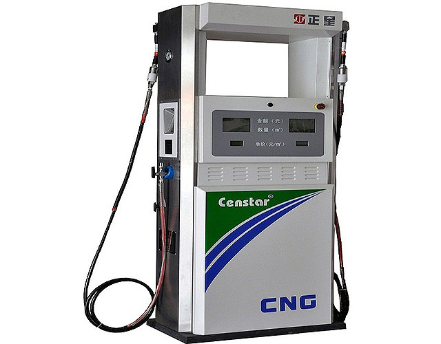
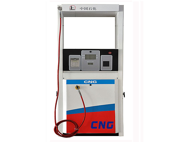
vapour recovery system Quality Supplier from China
Quality vapour recovery system supplier on sales from vapour recovery system manufacturer find China vapour recovery system factory, suppliers from
STAGE II VAPOUR RECOVERY
vapour recovery nozzles, vapour control valves, COAX hose assemblies, Safety Breaks and other accessories for Stage II vapour recovery. Some advantages of the ELAFLEX VR products are: n reliable products with a life expectancy of 10 years or more n slim design, lightweight and customer friendly n modular construction and interchangeable spare parts
Vapour Recovery System Low VOC Emission Assentech
VOCZero’s Thermal Regenerated Activated Carbon System, TRAC . VOCZero offers a range of Vapour Recovery Systems for recovery of relatively low concentrations of volatile organic compounds from systems are in particular well suited for areas, where extreme low VOC emission in the ppb ppm level is required, like in many petrochemical facilities.
PowerPoint Presentation
A recovery/recycling refrigerant machine removes refrigerant from the system and recycles the refrigerant for reuse. Antifreeze Recovery and Recycling Equipment The mixture of antifreeze and water in a vehicle’s cooling system will eventually need to be replaced.
Public Workshop to Discuss If Updates are Needed to the
impair effectiveness of vapor recovery system in controlling motor vehicle emissions Conduct a public workshop once every three years to review VRED List and to update as necessary Review VRED List when a written request is submitted Legal Requirements 4
The Automatic Monitoring System for active Vapour
The Automatic Monitoring System for active Vapour Recovery VAPORIX Flow, Control and Master Product information The automatic monitoring sys tem VAPORIX supplies infor mation on the functional state of the active vapour recovery and thus fulfils the require ments of the 21.BlmSchV (Ger man directive). As an automa tic monitoring system for the
NH Stage I/II Vapor Recovery Program
Benefits of Gasoline Vapor Recovery Reduces VOC emissions by up to 95 percent. Reduces exposure to toxics and carcinogens. GASOLINE
NGT Directs Oil Cos. To Install Vapour Recovery Systems At
NGT Directs Oil Cos. To Install Vapour Recovery Systems At All Petrol Pumps Etc By Oct 31 To Tap Harmful Compounds Entering Air [Read Order]
Flare gas recovery system MPR Industries
Flare gas recovery system. We will design, manufacture and install a bespoke system that absolutely fits our customers’ needs and gas characteristics. We can supply either a compressor (single or multi stage sliding vane, or single stage liquid ring technologies) or a plug and play skidded Flare Gas Recovery Unit.
Refrigerant Recovery Secrets ACHR News
• Vapor recovery: Vapor is drawn from the refrigeration unit into the recovery system. It passes through the compressor to the condenser, where cooling occurs. It passes through the compressor to the condenser, where cooling occurs.
Introduction to Condensate Recovery TLV A Steam
Condensate recovery is a process to reuse the water and sensible heat contained in the discharged condensate. Recovering condensate instead of throwing it away can lead to significant savings of energy, chemical treatment and make up water.
My Recovery System
The integration of My Recovery System’s easy to use, full back office platform and Vendor Transparency Solutions’ web based compliance management system with MBSi’s assignment volume, operating excellence and talent, formalizes a game changing component of
IPCO Power Fuel Treatment and Vapour Recovery
IPCO Power BV Spinel 400 3316 LG Dordrecht The Netherlands IPCO Power provides the shipping, power and petrochemical industry with environmental solutions for Fuel Treatment and Vapour Recovery.
Ejector Vapour Recovery Unit Crystal TCS
Ejector Vapour Recovery Unit are relatively new to this field, but are rapidly gaining acceptance over conventional recovery systems. We at Crystal TCS have performed intensive research and development for coming up with Ejector Solutions for Vapour Recovery Units.
Near Zero Flaring for the Refining Industry
ZEECO® Flare Gas Recovery (FGR) systems meet the strict compliance issues of NSPS Ja, and help refiners recoup their financial investment in the shortest amount of time. Our FGR systems work with your existing flare to achieve near zero flaring while recovering valuable waste gas that can be
Vapour recovery units Guidance on preventing and
VAPOUR RECOVERY UNITS GUIDANCE ON PREVENTING AND CONTROLLING TEMPERATURE EXCURSIONS IN CARBON BEDS iv FOREWORD This second edition, has been prepared by the EI’s Vapour Recovery Working Group, in consultation with vapour recovery unit (VRU) suppliers and the UK Health & Safety Executive.
Vapour Recovery System Alfons Haar
The closed vapour recovery system prevents emission of any vapours. • If the vacuum in any tank compartment exceeds 15mbar, the vapour transfer safety valve opens automatically. • The vapour recovery system as described permits safe simultaneous bottom loading with up to 5 loading arms at any depot designed to VOC Directive 94/63/EC. Note
Heat Recovery System in Domestic Refrigerator SlideShare
Figure shows Vapour Compression Refrigeration Cycle Figure 2.1 shows a typical vapour compression refrigeration system that can be broken into the different processes as explained below: Process 1 2 Low pressure liquid refrigerant in the evaporator absorbs heat from its surroundings, usually air, water or some other process liquid.
Day 2 topic 4 Vapour Recovery Systems Стр 2
Vapour recovery system design. When a shore vapour return arm or hose is presented to the ship for connection, it will have a hole drilled through it at the `12 o'clock' position, of a diameter to accommodate the stud. The IBC Code lays down the requirements needed for a ship to. meet the demands of returning the most toxic chemical vapours to. shore.
Vapour Recovery System CrystalTCS
Ejector vapour recovery systems operate in a form of a closed loop system. They suck the vapours and discharge them into the Intermediate stages of the Gas compressors. The Gas compressors further compress the vapour mixture and discharge to the gas supply lines.
Aircraft Systems: Aircraft Air Conditioning Systems
Vapor cycle air conditioning is used on most nonturbine aircraft that are equipped with air conditioning. However, it is not a source of pressurizing air as the air cycle system conditioned air is on turbine powered aircraft. The vapor cycle system only cools the cabin.
Aboveground Storage Tanks (AST) Phase II Enhanced Vapor
Vapor Recovery Throughput ofFacilities (gallons/year) Facilities Subjectto Phase II EVR (VR‐501) Throughput of Facilities Subject to Phase II EVR 2,761 106,782,636 187 55,536,802 Upgrade to Phase II EVR Breakdown Cost Average System Equipment Cost:
Nozzles for Active Vapour Recovery Systems
4. Vapour Recovery Test Confirm the vapour recovery rate is in the acceptable range by performing either a wet or dry test described in the “Nozzle Vapour Recovery Testing” section of this manual. Nozzle Operating Instructions 1. Insert the spout into the fill neck of the vehicle. 2. Lower the hose end of the nozzle so the spout engages the
Vapour Recovery
DRYVac™ is the first vapor recovery system to be normally offered with both inlet and outlet hydrocarbon monitoring systems. We believe that every process system should be fitted with enough instrumentation so it can adjust to the inlet conditions and monitor its effluent.
Vapour Recovery System Savas
Vapour Recovery System. GET A QUOTE. Water in the active parts of the transformer can have adverse effect on its lifetime. The indicative lifetime of insulation at 80 C and 1% moisture is around 40 years whereas with 3% moisture it is 10 Years. Furthermore the reliability and overload capacity of the transformer are also affected when moisture
Vapor Recovery Unit (VRU) Hy Bon
QSG225 Standard VRU Compressor. The HY BON/EDI QSG225 VRU is our standard oil flooded screw compressor package engineered for larger volume tank vapor recovery applications. Our QSG225 packages have a gas volume range starting at 70 MSCFD and maxing out at 300 MSCFD. The unit is powered by a 75 horsepower electric motor and is engineered for up to 2% H2S concentration.
Overview of Vapor Absorption Cooling Systems
Vapor absorption system allows use of variable heat sources: directly using a gas burner, recovering waste heat in the form of hot water or low pressure steam, or boiler generated hot water or steam.
PowerPoint Presentation
Existing double wall piping can only remain in place if the piping is approved for use by UL for VPH monitoring and can operate in accordance with Section 25290.1 (VPH, liquid/vapor tight). Not recommended. Vent/vapor recovery also become subject to the requirements of Section 25290.1 (VPH, liquid/vapor tight). System subject to ELD testing.
Petroleum Top Loading Arm Options, Vapour Recovery Arm
An explosion proof electrical control system to continually monitor static charge accumulation in the vehicle. Communicates with the DCS to allow operations to start/carry on only when the static accumulation is below recommended levels
Automatic Controls for Industrial Refrigeration Systems
REFRIGERATION & AIR CONDITIONING DIVISION Automatic Controls for Industrial Refrigeration Systems Application Handbook MAKING MODERN LIVING POSSIBLE