
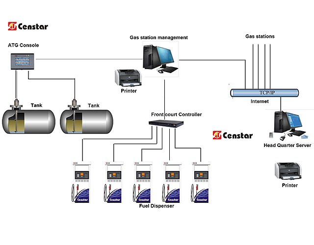
tank gauging system schematic diagram
Recommend Products


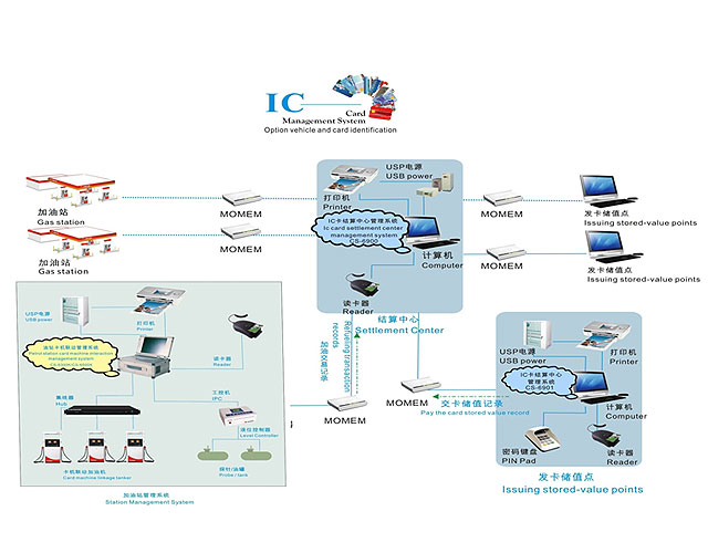
Tank Gauging System ZYcj^hXdc9i^ EdgXYij
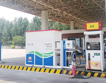
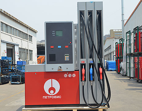
1. System Description The TankRadar Rex System is a monitoring and control system for tank level gauging. The system can interface various sensors, such as temperature and pressure sensors, for complete inventory control. There is a distributed intelligence in the various units of the system. The units continuously collect and process information.

Ford Truck Technical Drawings and Schematics Section E
Fuel System and Related Parts (Evaporative Emission System (with In Cab Fuel Tank) 1970 F100 6 Cyl. 240, 300 and 8 Cyl. 302, 360, 390 engines 1200 x 1498, 301K
Franklin Fueling Systems Americas
Protect and extend the life of vital petroleum system electrical and data wiring with the Cable Tight™ wire management system. Get your entire company trained and certified on all courses in five days or get specialized training in one or two days with our live, Total System Solutions™ Training Workshops.
Open Roads Forum: Tech Issues: wiring diagram for
Wayne Dohnal. The wires from the tank go to a resistor pack, then 2 wires from there go to the monitor panel. Take a look at the 3rd post in this thread Holding Tank Sensor Wiring. Here's a picture of a resistor pack on Censtar Censtar resistor pack.
Schematic Reactor Auto Sampling System 2 YouTube
Schematic Reactor Auto Sampling System 2. Skip navigation Sign in. Search. HHO 30 Amp PWM circuit diagram + EFIE Duration: Tank Gauging System

Reference Gauging System for a Small Scale Liquid NASA
Reference Gauging System for a Small Scale Liquid Hydrogen Tank 2 tank reference gauging system. A counterbalance removes the tare weight of the tank. Since the tank is much heavier than the Figure 1 is a schematic diagram showing the major components and the overall design concept of the
UST Systems: Inspecting And Maintaining Sumps And Spill
UST Systems: Inspecting And Maintaining Sumps And Spill Buckets 5 Transition/Intermediate Sumps Transition/intermediate sumps are less common than other sumps, but can be found along the piping runs that connect the tanks to the dispensers, and are designed to provide access to the piping. Transition sumps are
Well Pump & Pressure Tank Diagram Clean Water Store
Tank Tee Connets water line from pump to pressure tank and service line from tank to house. Taps are provided to accept Pressure Switch, Pressure Gauge, Drain Valve, Relief Valve, Sniffer Valve, etc. 9. Drain Valve Drain easy draining of the system. 10. Relief Valve Protects against pressure build up.
Garnet Instruments Ltd. Liquid Level Measurement
Garnet is the source for leading edge solutions in liquid level measurement. Our patented SeeLeveL™ design for tank level gauging in transport tank truck applications not only provides accurate level information but is also the first totally automated spill prevention system for applications
Fuel Tank Schematic Wiring Diagram Database
Fuel system schematics and fuel gauge troubleshooting ford truck technical diagrams and schematics boat fuel tank wiring diagram magicalillusions help with dual tank selector valve wiring what is the wiring diagram for a chevrolet dual tank gas tank sending unit wiring diagram help page 1 iboats sst srs day tank manual simplex inc wiring
Tank Gauging Systems Products Liquid Level Systems
The Tank Gauging System measures continuously the level, volume and temperature of the contents of ballast water, fresh water, cargo, fuel oil, bilge and mud tanks. Additionally, the vessel’s draught can be measured. High and low alarms can also be set. Series 500 liquid level transmitters ensure precise tank content and draught readings.
Fuel Tank System
The new fuel tank system was designed to accommodate future LEV 2 emission requirements. This was accomplished by moving as many components and fuel lines as possible inside the fuel tanks, to minimize hydrocarbon emissions. A flexible metal crossover hose assembly replaces the former rubber one, because the permeable rubber allowed a small
SELMA SELMA Ship Electric Marine Control
SELMA Ship Electric Marine Control is a marine engineering and manufacturing company specialising in the design, development and installation of integrated marine electrical, automation and control systems in ships worldwide.
Exmark Fuel Tanks and Fuel System Parts
Exmark Fuel Tanks and Parts Exmark Fuel Tanks are designed for maximum fuel capacity and durability on each Exmark model. Along with fuel tanks, Exmark Fuel related parts including Fuel Pumps, Fuel Caps, Fuel Gauges and more can be found exclusively through an
Wiring schematic for gas actuator/switch dual tank Chevy
circuit identification for wiring diagram: 30 pink fuel gauge to selector valve 53 lt. grn valve release solenoid to control box 54 dk. grn control box to shield 139 pink or pink/black feed, ign sw, "accsy and on" controlled 150 black ground circuit, direct 830 pink/black
Tank gauging system Rosemount Tank Radar AB
FIG. 3 is a functional block diagram of a tank gauging system according to a preferred embodiment of the first aspect of the present invention. FIG. 4 is a diagram schematically illustrating a power supply characteristic according to the first aspect of the invention.
Fuel System Diagrams Aeromotive, Inc
Fuel System Diagrams. Then return here for diagrams to complete your system. The following are the basic solutions to the most common systems. For more specific diagrams, or variables of the following, please call tech at 913 647 7300 Stealth 340 Diagrams Phantom 200 & 340, Stealth 340 Fuel Cells, Stealth 340 Performance Muscle Tanks.
Fuel The Boeing 737 Technical Site
The fuel tank was instrumented with gas sample tubing and thermocouples to allow for a measurement of fuel tank inerting and heating during the testing. The FAA developed an in flight gas sampling system, integrated with eight oxygen analyzers, to continuously monitor the ullage oxygen concentration at eight different locations.
TANKERS & CHEMICAL
DRAFT GAUGING SYSTEM Schematic diagram Experience on board ships teaches how much problem give submersed electronic level sensor due to poor

Airbus A320 Fuel System Schematic
gauging Airbus A320, A330, A340, A350 XWB, A400M / Boeing 737, successfully tank inerting system has been established in this study and the schematic diagram of the of the FAA onboard inert gas generation system on an Airbus A320. Airbus. A319 100. Speed limitation when Ram Air

TLS 350 Automatic Tank Gauge Veeder Root
TLS 350 Automatic Tank Gauging System A legacy of reliability With over 20 years of global experience as the most installed automatic tank gauge in the industry, the TLS 350 Automatic Tank Gauge provides users with a highly flexible design for meeting compliance and fuel management needs.

circuit schematic Circuit Wiring Diagrams
The above schematic is just and illustration for the 1967 Ford F 100 and F 350 Wiring Diagram/Electrical System Schematic. This wiring diagrams applied for 1967 Ford Truck F 100 and F 350 series. Here you will find 13 diagrams depicting the 1967 Ford Truck F 100 wiring installation including truck auxiliary tank diagram, truck courtesy light wiring, exterior lights and turn signals, truck
Finch II display Titan Logix Corp
The Finch II is designed for use with Titan's proven TD80 liquid level gauging system for mobile tankers. It is an enhanced version of Titan's classic external display, the Finch 5332E. Five digit LED display for a greater choice of display units
Radar Level Transmitters AutomationWiki
Radar level measurement technique offer extremely accurate and reliable detection of level in storage tanks and process vessels. The performance of radar level transmitters remains unaffected by heavy vapors and mostly all other physical properties of the fluid under level measurement (except dielectric constant of the liquid). Disadvantages
F2000EX EASY 02 28 00 ATA 28 FUEL SYSTEM CODDE 1
FUSELAGE TANK EMPTYING SEQUENCE The fuel gauging system and the fuel transfer sequence are monitored and controlled by the FQMC. The FQMC manages the fuel transfer sequences so that the fuel from the forward and rear tanks is used first. When these tanks are emplty, the FQMC uses fuel from LH and RH center and wings tanks.

CaravansPlus Caravan Water Tank Gauges Delivered Fast
Compare Caravan Water Tank Gauges from Premium Brands like JRV, RV Electronics, Setec. Australias Favourite Online Shop for Caravan Accessories and Spare Parts.

Wiring diagram for 1998 chevrolet s10 2.2 fuel system Fixya
Haynes Manual 24071 includes wire diagrams for all components. On the injector you have a pink and dark blue wire both are hot and signal wires. The only ground in the system is on the fuel pump and sender unit. Diagram 12 26 in the haynes maual.

Tank gauging system ITT Corporation
FIG. 1 is a schematic diagram of the tank gauging system of this invention using a plurality of bubbler tubes. FIG. 2 is a graph of the pressure within a bubbler tube over time as the gas is valved therethrough. FIGS. 3A and 3B show elevational
An Engineering Guide to Modern Fuel Systems
An Engineering Guide to Modern Fuel Systems This publication is intended as a resource for designers, installers, and system operators. In this document we highlight the typical indoor components and operational requirements of modern diesel fuel or fuel oil systems. Critical Fuel
Well Pump & Pressure Tank Diagram Well Water Report
Well Pump & Pressure Tank Diagram. I have been a member for years and it’s a great resource. See them at Here (below) are the main components of the most modern submersible pump and pressure tank systems. Your well system may not have all these parts but at the least, you have the submersible well pump, check valve, pressure switch and pressure tank.
Well and Water System Diagram
Should be used on any system where the pump could develop pressure that exceeds the maximum system rating. (18) Pressure Gauge Measures water pressure in Pressure Tank. (19) Pressure Switch Signals the pump to start when the water system drops to a pre set low pressure, and to stop when the high pressure mark is reached. (20) Safety Switch

SERVICE MANUAL Navistar
LoneStar® and ProStar® Chassis Built January, 2007 and After — ELECTRICAL CIRCUIT DIAGRAMS iii . REMOTE RADIO — N/AMP AND N/WIRED REMOTE AND N/DRIVER INTERFACE DISPLAY,
Electronic Line Leak Detection Censtar
Automatic Tank Gauging; Electronic Line Leak Detection Censtar. Description. Solves your mechanical Leak testing Problems Intelligent electronic systems virtually eliminate "False Alarms" Self diagnostic system eliminates the required functional testing for mechanical leak detectors. No site shutdown to perform lph test
Marine Holding Tank Sensors: How do you Know When the
The Scad Solo will monitor only one tank, and the kit comes with one sensor and one display panel. To monitor two tanks, Scad suggests installing a rotary switch at the display panel, wiring it to sensors on the tanks and simply switching from one tank to the other as needed.
FALCON 7X 02 28 05 ATA 28 FUEL SYSTEM / 4 DGT97831
The tanks are pressurized by LP bleed air from No 1 and No 3 engines. It is available whenever engines 1 or 3 are operating without crew interaction. The pressure is regulated at 2.9 psi. The pressure can be read on a tank pressure gauge in the rear compartment. ¾ Refer to "System Protections" section for information on Overpressure and negative
dual fuel tank wiring diagram/ help Page 2
I am getting ready to do my fuel system and have do idea how to it. I am going to start a new thread on the entire fuel system rigging; plumbing, wiring, filters, pumps, all the stuff that goes into rigging a proper fuel system for dual tanks. Sorry about the thread jack Matt. Thank you.
Well head & pressure tank pictures / illustrations
Tank Tee Details. Notice the tank tee assembly is a quick and compact way to install the tank while incorporating a nipple & union, a recommended check valve, pressure switch, pressure gauge, pop off valve, and a faucet to get emergency water out ot the system even if the water is turned off to the house by the ball valve nearby. CLICK TO ENLARGE.
Chevy Truck Dual Tank Fuel Wiring Diagram Wiring Forums
Or you are a student, or perhaps even you that just need to know regarding Chevy Truck Dual Tank Fuel Wiring Diagram. Chevy S10 Fuel Gauge Wiring Diagram. Fuel Sending Unit Wiring, size: 800 x 600 px, source:

2500 Automatic Tank Gauge
2500 Automatic Tank Gauge 2 Installation and Operations Manual Getting Acquainted with the 2500 Automatic Tank Gauge Systems The 2500 series of Automatic Tank Gauges (ATG) are float and tape operated instruments designed to provide continuous liquid level measurement in bulk storage applications. The gauge can be installed on the tank roof or at
Learn How to Read P&ID Drawings A Complete Guide
Tank gauging system is used to calculate the quantity of the liquid stored in the tank at any given time. Based on the diameter, level, and temperature it will calculate the quantity of the liquid stored in the tank. QI is a quantity indicator. In the last part of this video, let check what is going out of the tank.
Piping and instrumentation diagram Wikipedia
A piping and instrumentation diagram (P&ID) is defined by the Institute of Instrumentation and Control as follows: A diagram which shows the interconnection of process equipment and the instrumentation used to control the process. In the process industry, a standard set of symbols is used to prepare drawings of processes.
C130 Fuel System Flashcards Quizlet
Main Tanks: Insert a pre marked dipstick in the filler cap opening. Auxillary Tanks: Magnetic Sight Gauge External Tanks: Cannot be manually checked.
Website
tank that is visible on the schematic image to view the details of the selected tank. The administrator can control the hotspots displayed on the schematic diagram by editing the file, located in the TMnData Language folders. This file contains the tank name and the co ordinates that are
Diagnosing dual tank balance module The Truck Stop
For single fuel tank vehicles, the fuel gauge includes the following functions: The level sensor in the fuel gauge sender produces a resistance of about 40 ohms (Gas)/0 ohms (Diesel) empty and about 250 ohms (Gas)/90 ohms (Diesel) full. A short to ground in the sender or the wiring provides a fully empty indication.