road tanker vapour recovery system
Recommend Products
A report produced for the European Commission,
15. During the unloading of a ship's tank air or inert gas is drawn into the tank as the liquid level inside drops. This cannot lead to an emission of VOC to the atmosphere because while the liquid level is falling the pressure inside the tank will always be slightly below atmospheric pressure and there will be a net inflow of air into the tank.
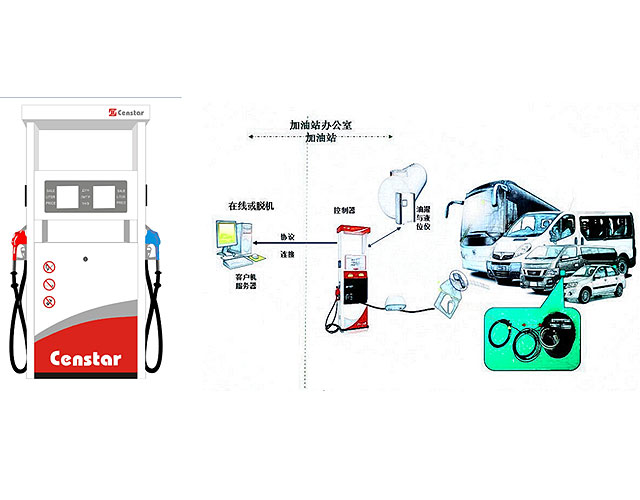
Vehicle fuel tank vapor recovery system (Patent)
A fuel filler system is described, comprising: a fuel tank; an open ended fuel filler tube connected to the tank and having a vapor vent leading to a canister, the open end of the filler tube closed by a removable threaded filler cap: and internal threads cooperating with the filler cap threads for
Vapor Recovery System.
M978 HEMTT tanker. Vapor Recovery System. on the end of the line is compatible with the 4 inch quick disconnect, vapor recovery connections at a. majority of fuel depots. Tank and Pump Unit. The tank and pump unit consists of a 50 GPM pumping assembly, two 500 or. 600 gallon aluminum tanks, and related equipment.
Standards and Best Practice Guidelines for Vapour Recovery
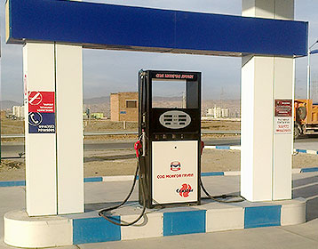
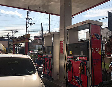
Stage 1 vapour recovery (VR1) at petrol service stations limits the emissions of volatile organic compounds (VOCs) that result from unloading petrol from a road tanker into petrol service station storage tanks. When petrol is transferred from a delivery tanker to an underground storage tank, a slight
Vapour recoVery solutions from sGs oil, Gas and chemicals
means a vapour recovery unit must be installed that is able to remove and recover 98% of the petrol vapour generated during the loading of petrol into road tankers. To ensure the environment is being properly protected the VRU must be regularly tested to demonstrate that the amount of hydrocarbon emitted into the air is below the limit.
Vapour recovery at service stations
Vapour recovery at service stations. VR1 captures displaced vapours from storage tanks when a tanker delivers petrol to a service station, while VR2 captures displaced vapours at the bowser while a motorist refuels. Update to Standards and Best Practice Guidelines for Vapour Recovery at Petrol Service Stations.
Vapour Recovery Loading Arms Loadtec
LOADTEC VAPOUR RECOVERY LOADING ARMS are designed to capture the vapours displaced from the road tanker or rail tanker, during filling operations. The most common method for collection of vapours during filling, is via a cone shaped plug that closes the open
Road Tanker Bottom Loading YouTube
Petroleum road tanker bottom loading system designed and installed by IFC Inflow at a UK Oil Distribution depot. The loading system comprises the overfill an
Send Us A Message Gas Processing Equipment and Vapor
Oil Tank Vapor Recovery Model BA. The unit is mounted on a skid, completely factory assembled, tested prior to shipment, and comes with all required equipment, including instrumentation, piping, and
Aluminium Air Operated Vapour Vents Liquip Victoria
Aluminium Air Operated Vapour Vents. The sequencing valve can be blanked if not required. The poppet opens inwards to prevent leakage and spills from product surge in the event of a tanker rollover. Operating Pressure Operating air pressure 120 kPa to 900kPa. (Normal 500kPa).
Summary Guidance Note for Service Station Operators on
return hose at the road tanker end first and then at the storage tank end. This ensures petrol vapour displaced from the petrol storage tanks is returned to the road tanker. Do not exceed the designated number of tanker compartments that can be simultaneously discharged. The tanker driver must remain near the tanker and keep a constant watch on hoses and connections during unloading.
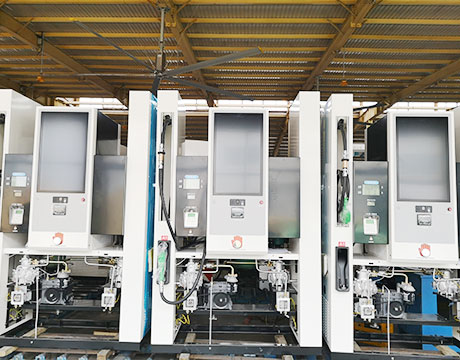
Vapour Recovery System Alfons Haar
The closed vapour recovery system prevents emission of any vapours. • If the vacuum in any tank compartment exceeds 15mbar, the vapour transfer safety valve opens automatically. • The vapour recovery system as described permits safe simultaneous bottom loading with up to 5 loading arms at any depot designed to VOC Directive 94/63/EC. Note
Vapor Recovery from Truck Loading Chemical plant design
Vapor Recovery from Truck Loading. This is a standard 'loading arm' station for road tanker filling. The grounding line is also an instrument conductor for the filling rate monitoring, the over fill protection and net transfer control. The control system is either a complex, SCADA like system or a simple local control panel and batch controller,
Emco Wheaton Bottom Loading & Vapour Recovery System
Emco Wheaton provides complete solutions for tank truck loading and unloading and vapour recovery. From tank truck systems and API couplers to loading arms a
Gasoline Diesel Rack Loading and Operating Procedure 8
GASOLINE/DIESEL RACK LOADING AND OPERATING PROCEDURE Authorized by: Operations Department Moc # 03 06 12 412 033 Carr 8/9/12 Page 3 of 18 GENERAL GUIDELINES 1. Turn off all electronic devices (cell phones and CB radios) before entering the terminal entrance. 2. NO SMOKING OR OPEN FLAMES ARE PERMITTED AT THE TERMINAL. 3. Speed Limit is 5 mph. 4.
Vapor Recovery Systems at Best Price in India
Vapour Recovery Systems Carbon Tech VRUTM find application in Storage Tank Farms & Truck, Rail & Marine loading facilities for Petroleum & Petrochemicals. The recovery process is based on adsorption on activated carbon .The activated carbon is then regenerated by Vacuum.
Fuel Vapour Recovery Adapter Alpeco Ltd
A non return valve with virtually no pressure drop. This valve is specifically designed for vapour recovery applications. VAP400AIC: 4” vapour adaptor fitted with a dust cap, an interlock for interlocking brakes and a vapour dump valve when a vapour hose is connected: PKL400 VAP
Vapour return on road tankers Solvents
inspectors demanding that road tankers have vapour return as part of a site’s VOC reduction strategy. The SIA’s position on vapour return for road tankers for most VOCs remains unchanged and is summarised as follows: 1. Even when vapour return takes place, the vapours are lost to atmosphere on
Bottom Loading and Vapor Recovery System Emco Wheaton
The benefits of a Vapor Recovery System are that it is safer, faster, cleaner and provides the ability for vapor return, vapor reduction, cost reduction, and closed filling. Our Bottom Loading Systems usually include Vapor Return facilities at little extra cost.
VAPOUR CONTROL SYSTEMS Rules and standards
106 Tanker vapour connection : The point in a tanker's fixed vapour co llection system where it connects to a vapour collection hose or arm. 107 Terminal vapour connection: The point in a terminal's vapour collection system where it connects to a vapour collection hose or a vapour collection arm.
RULE 461 Gasoline Transfer and Dispensing
forth in the CARB CP 201 (Certification Procedure for Vapor Recovery Systems. at Gasoline dispensing facilities) Sections 3 through 9. (12) Fueling Position A fuel dispensing unit consisting of nozzle(s) and meter(s) with the capability to deliver only one fuel product at one time.
Vapor Recovery Executive Orders California Air Resources
For Gasoline Dispensing Facilities (GDFs) with no Phase II Vapor Recovery System: Executive Order NVR 1 D (Low Permeation Hoses and Enhanced Conventional (ECO) Nozzles) EVR system determination letters are issued by the State Water Resources Control Board to assure EVR systems will not conflict with underground storage tank statutory requirements.
Vapour Recovery Inspection and Testing Stage 1B Vapour
This is achieved by diverting the vapour displaced through the tank vent back to the road tanker for removal from site and subsequent recovery at the distribution terminal. The vapour recovery system will have one tanker connection point which can be below or above ground which will come complete with a poppet self sealing adaptor and a flame arrester approved to EN ISO 16852.
vapour recovery Flotech Performance Systems
Bottom Loading with Vapour Recovery Suitable for bottom loading of road tankers with API Coupler Connections. The arms can be designed to connect to side of the tanker and also cross over to suit the configuration of the tanker connections.
Vapour Recovery Road Tanker Spares
Vapour recovery is the process of recovering the vapours of gasoline or other fuels, so that they do not escape into the atmosphere. We supply a range of Vapor recovery equipment for road fuel tankers.
Research report Flow performance testing of vapour
displaced vapour to a terminal’s vapour recovery unit. Road tankers are required by the directive to display a plate giving the maximum number of compartments that may be filled simultaneously without any vapour being expelled to atmosphere (as a result of excessive back pressure being generated); however, no test procedure or protocol to determine that number is defined.
Comparison of tanker drivers' occupational exposures
The road tanker loads delivered consisted of oxygenated and reformulated petrol (E95 and E98 brands), which contained on average 13% oxygenates. Before the installation of the vapour recovery system, the geometric mean (GM) concentration of aliphatic hydrocarbons was 65 mg m
Vapour Recovery
Today, SYMEX Americas DRYVac™ System is the ONLY proven, modernized, and completely automated dry vapor recovery system on Earth with a proven track record of excellent performance. In addition, each new DRYVac™ System is supplied with our technically advanced FlowMax™carbon.
Tank Truck Products Civacon
Civacon Products Designed for safeguarding people and the environment. Civacon is dedicated to designing, manufacturing and distributing world class solutions for the safe handling and transporting of petroleum products.
BMW and MINI Fuel Vapor Recovery Systems Charcoal
Almost all vehicles on the road today have a raw fuel, vapor recovery system. The fuel tank on your BMW or MINI needs to vent as the fuel is drawn out and used in the engine. If there were no provision for venting, a vacuum would develop in the tank and soon the fuel pump would not be able to draw the fuel out and deliver it to the engine.
Vapor Transfer Vents to transfer displaced vapors
As a key component in the vapor recovery system, the vapor transfer vent (VTV), fitted to the Manhole Cover, provides the means to transfer displaced vapors to and from the tanker. Supplied air operated and sequenced with the emergency valve, our Vapor Transfer Vents ensure vapors are transferred safely during the loading and unloading process.
AP 42 Section 5.2: Transportation And Marketing Of
Tank truck loading with vapor recovery. The saturation factor, S, represents the expelled vapor's fractional approach to saturation, and it accounts for the variations observed in emission rates from the different unloading and loading methods.
Vapour Recovery System UK Petrol Diesel Petrochemicals
Vapour Recovery System VRU The prevailing method of vapour recovery globally is, and has been for decades, adsorption of the VOCs (volatile organic compounds VOC are chemicals that have high vapour pressure like Petrol, Diesel, Methanol, Crude Oil, Benzene, paints
Oil & Gas Vapor Recovery Systems PetroGas Systems
Absorption. VOC recovery in a Refrigerated Lean Oil Absorption system consists of a vapor/air mixture that enters the bottom of a packed tower, counter flows upward, and impinges on absorbent, wetted packing. A chilled absorbent fluid enters the top of the tower and begins a
Transportation Fuel Delivery Parker Hannifin
with LPG road tanker builder, a pneumatic brake interlock control system. This unit is designed to prevent the “roll away” of rigid chassis, LPG road tankers during loading and un loading due to the incorrect use of the vehicles parking brake. The pneumatic circuitry is housed inside an acrylic manifold with the pneumatic products being affixed
Vapour recovery at service stations
Vapour recovery control equipment aims to capture petrol vapours before they enter the atmosphere. They are designed in two stages VR1 and VR2. VR1 captures displaced vapours from storage tanks when a tanker delivers petrol to a service station, while VR2 captures displaced vapours at the bowser while a motorist refuels.
Retail Site Vapour Recovery Soliflo
Retail Site Vapour Recovery VR Refiner System On site vapour processing ensures fuel station retailers have full control of their most valued asset, thus maximising profit and fuel margins. Road tankers return to depot with Lower Explosive Limit;
VAPOUR RECOVERY Zeeco, Inc.
of road tankers, ships and tank breathing, with vapour flow capacities from 100m3/ hr or lower with rates of up to 1000m3/ hr to 5000m3/hr becoming increasingly more common. Currently, the largest system is handling flows exceeding 30,000m3/hr. Activated carbon vapour recovery units largely remain the preferred technology and
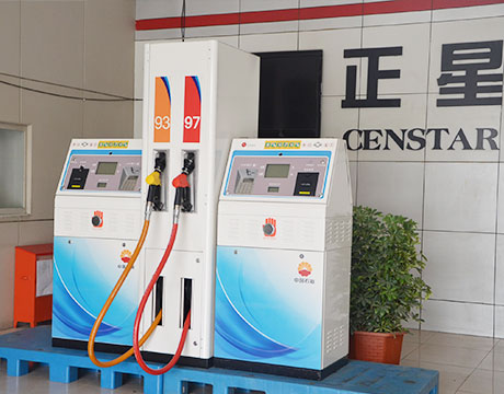
VAPOUR RECOVERY Kalymnos Fuel Engineering
The Vapour Recovery Couplers ensure the opening and vapor transfer through the VR Adaptor of the road tanker. The KFE has Couplers for both VRU of the loading gantry and for the vapor transfer piping to the filling station. Different versions are available for flexibility and adaptation to each user request.
Final Crude Oil and Petroleum Product Terminals IFC
CRUDE OIL AND PETROLEUM PRODUCT TERMINALS AP 2 WORLD BANK GROUP 1.0 Industry Specific Impacts and Management The following section provides a summary of EHS issues associated with crude oil and petroleum product terminals that occur during the operation phases of a facility, along with recommendations for their management.
DRIVER CHECKLIST FOR LOADING AND UNLOADING
USING THE API COLOR SYMBOL SYSTEM TO MARK EQUIPMENT AND VEHICLES FOR PRODUCT IDENTIFICATION AT GASOLINE DISPENSING FACILITIES AND DISTRIBUTION TERMINALS. (3rd Edition July 2006) NC Fire Code requires each fill pipe for motor fuel at a service station must have a label or must be painted a particular color to represent the product in the tank.
Fixing 1970s Evaporation Control Systems Allpar
Chrysler’s version was dubbed “Vapor Saver” or “ECS” (Evaporation Control System). The 1970 71 ECS used a complicated fuel tank, which had a small inner tank at the top connected to the main tank chamber by a very small passageway to prevent overfilling.
Road Tanker Safety design, equipment and the human
Vapor recovery equipment (valves and vents) are designed to channel vapors to the correct location rather than causing a build up in the road tankers or being vented into the atmosphere. When loading or unloading liquids, the liquid moving through the pipes, top loading arms and bottom loading arms generate static electricity.
Onboard refueling vapor recovery Wikipedia
Onboard refueling vapor recovery. However, an ORVR system is able to retain those emissions, delivering them to the vehicle's carbon filled canister and then to dispose of those vapors by adding them to the engine intake manifold and the stream of fuel supplying the engine, during normal operation.
Adaptors Liquip Victoria
When connected to a female vapour coupler the adaptor poppet is pushed inwards to allow vapour flow and the coupler also pushes the striker plate of the adaptor forward to provide an electrical signal that the vapour recovery system is conencted. VCM3 Series. the VCM3 series is a poppet sealed cam and groove connection for turck vapour return lines.