gas compressor station block diagram
Recommend Products

LNG Plant Overview Murmanshelf
LNG Plant Overview Seminar with Supplier Association Murmanshelf Murmansk, 15 May 2012 •Introduction Liquefied Natural Gas (LNG) •Block diagram of LNG plant compressor Compressor suction drum Propane condenser Kettle heat exchanger Expander (Sakhalin) 17
The basics of a compressor station
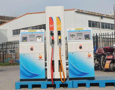
3. Station Turbine Compressor The station’s compressor building(s) house(s) the turbine compressor that is the heart of the compressor station. These consist of two main components: a gas turbine and a compressor. The compressor mechanically re pressurizes the gas in the pipeline using an impellor similar to that of a water pump in an automobile.
Solar Powered Air Compressors Axiom Technologies, LLC
SOLAR AIR COMPRESSOR BLOCK DIAGRAM. Dual Solar Air Compressor. Eliminates natural gas emissions sourced by instruments at the well site Built and tested for dependability. More than 3,600 hours running without any maintenance (Not used for the ZEUS Compressor) Station 3 (Not used for the ZEUS Compressor) Station 4 (Not used for the
GAS TURBINES IN SIMPLE CYCLE & COMBINED CYCLE
The gas turbine is the most versatile item of turbomachinery today. It can be used in several different modes in critical industries such as power generation, oil and gas, process plants, aviation, as well domestic and smaller related industries. A gas turbine essentially brings together air that it compresses in its compressor module, and
Single Stage Compressor Control
percent flow is not adequate for the compressor’s head, the recycle valve will be opened. The algorithm is used to generate a setpoint for the specialized PID loop. The surge control algorithm executes in less than 25 ms. The following simplified functional block diagram illustrates the features of the algorithm.

Piping and instrumentation diagram Wikipedia
A piping and instrumentation diagram (P&ID) is defined by the Institute of Instrumentation and Control as follows: A diagram which shows the interconnection of process equipment and the instrumentation used to control the process. In the process industry, a standard set of symbols is used to prepare drawings of processes.
Liquefied Natural Gas Department of Energy
increase imports of natural gas from outside North America. Net imports of natural gas are projected to supply 19 percent of total U.S. consumption in 2010 (4.9 Tcf) and 28 percent in 2025 (8.7 Tcf).3 This natural gas will be transported via ship in the form of liquefied natural gas
Compressed Air System Schematic Diagram
Most air Fig 3: Schematic diagram of Solar based air compressor for inflating tyres. to compressor, t2 compressed air temperature, tg3 temperature of the Diagram of a system with heat regeneration and internal combustion is pre Schematic diagram of combined air/steam cycle
Load Sharing Optimization of Parallel Compressors
stations. Natural gas pipelines are used to deliver gas from A block diagram of a typical pipeline com pressor station II. STEADY STATEMODELOFTHEPLANT FOCUSEDONENERGYCONSUMPTION The major operating cost of a compressor station i s constituted by either the energy consumption of mot ors in case where electrical VSD are present or
Solved: Also Assume, Heat Transfer Between Cycles Takes Pl
Show transcribed image text A 250 MW combined gas steam power plant consists of a non ideal gas turbine topping cycle and a bottoming cycle that's a nonidcal Rankine cycle with a single open feedwater heater. Draw a clearly labeled system block diagram using the station numbers shown on the T s diagram at right, labeling the components, working fluid flow and energy transfer directions.
Understanding Centrifugal Compressor Performance in a
made to the compressor and driver. Alternatively, lower cost process system modifications can be used to debottleneck a compressor limit. Figure 1 shows a block diagram of a compressor and the connect ed process system components. The connected process system and com pressor performance must be thoroughly evaluated as a single system to determine
Installation Manual for CNG Kit Gasoline/CNG
# 2. Electronically controlled gas injection (capable of achieving EURO IV Emission Standard) Can be used on gasoline engines with carburetor or fuel injection systems, as well as on diesel engines that have been converted to operate on natural gas (can be used on turbo engines).
How Gas Turbines Power Plants Work. How Gas Turbine Works?
Learn how gas turbine power plants work in this article. What are the main sections of a gas turbine? What are the main performance factors? Answers to these questions can be found here explained in simple terms. Gas turbine functions in the same way as the Internal Combustion engine. It sucks in air from the atmosphere, compresses it. The fuel is injected and ignited.
Process Design Basics for Stations Facility
Process flow diagram 1. Purpose. The purpose of this article is to establish the design basis electrical system Front End Engineering Design (FEED) and data design or standards uses in the gathering stations facility will be built. Electrical system design refers to the process flow diagram and utility flow diagrams, existing data of flow diagram contain of equipments that’s requires
(PDF) Reliability analysis of a natural gas compression
The aim of our contribution is to provide the mathematical model of actual natural gas compression station which is situated in the Czech Republic and its surrounding gas pipeline network with
Subsea Compression Now and the Future
Typical Subsea Process Block Diagram Building Blocks Water Treatment Oil Treatment Gas Liquid Separation Gas Treatment P C P Station 1985 Concept Qualification Project Conceptual development Operating since Sept 2015 Subsea Compression Now and the Future Slide 14 Today Tomorrow (SCS 2.0) Less than half size, weight and cost
How Does the Natural Gas Delivery System Work? American
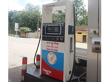
Compressor Stations. Compressor stations are located approximately every 50 to 60 miles along each pipeline to boost the pressure that is lost through the friction of the natural gas moving through the steel pipe. Many compressor stations are completely automated, so the equipment can be started or stopped from a pipeline's central control room.
Standardize compressor station design to reduce project
Standardize compressor station design to reduce project costs and time line. S. Mokhatab, Consultant, Halifax, Nova Scotia, Canada; T. Cleveland, Cleveland Engineering Services Ltd., Calgary, Alberta, Canada; and S. P. dos Santos, At Work Rio Engineering and Consulting Ltd., Rio de Janeiro, Brazil A principal component of any gas transmission system is the compressor station.
US8052398B2 Reciprocating gas compressor with speed
FIG. 1 is a block diagram of a reciprocating gas compressor system. FIG. 2 illustrates the piping response to pulsation of an example compressor system. FIG. 3 illustrates the piping response of the example compressor system, with the compressor operating at the worst case fixed engine speed.
Oil facility PetroWiki
Fig. 1 is a block diagram of a simple oil facility. Each of the blocks is described here, except for gas dehydration, which is covered in Gas Facilities. Fig. 1—Typical oil facility. the total liquid in the tank increases even further, with additional gas flashing at a higher pressure, reducing compressor
Compressor Wikipedia
The photograph on the right depicts a three stage diaphragm compressor used to compress hydrogen gas to 6,000 psi (41 MPa) for use in a prototype compressed hydrogen and compressed natural gas (CNG) fueling station built in downtown Phoenix, Arizona by the Arizona Public Service company (an electric utilities company).
Natural gas compression plant schematic Mobil™
Natural gas compression plant . Explore equipment and application specific to your industry in the below schematic. You can click on red hotspots in the schematic or on items in the right hand equipment menu to see corresponding lubricant information. You can then click on a specific lubricant to see more detail about that product.
Gas Turbine Power Plant Layout & Schematic Diagram
A generating station which employs a gas turbine as the prime mover for the generation of electrical energy is known as a gas turbine power plant. In a gas turbine power plant, air is used as the working fluid. The air is compressed by the compressor and is led to the combustion chamber where heat is added to the air, thus raising its temperature.
Gas facility PetroWiki
A gas facility encompasses the equipment between the gas wells and the pipeline or other transportation method. The purpose of the gas facility is to remove impurities and contaminants from the gas, remove liquids and solids, and prepare the gas to meet the sales requirements of the purchaser. Fig. 1 is a block diagram of a simple gas
Fundamentals Of Gas Pipeline Metering Stations Pipeline
Pipeline gas metering stations are designed for simultaneous, continuous analysis of the quality and quantity of natural gas being transferred in a pipeline, as follows: Upper calorific value, which is the latent energy content of a
Pipeline Stations: From Pre Commissioning to Start Up
• Gas discharge system (pipeline) or recycle loop for start up and initial operation. • Main units, including compressor packages. • Gas suction system (pipeline). Reprioritizing is the key for a successful and timely commissioning of a compressor station.
Gas Train Schematic Best Place to Find Wiring and
Gas Train Schematic Best Place to Find Wiring and Datasheet Resources. Skip to content . . Best Place to Find Wiring and Datasheet Resources. Lost Something? Diagram Fuel Filter Cap Schematic Wiring Diagramdiagram Fuel Filter Cap Wiring Diagram Fuel Train Diagram Diagram Sign In To Download Full Size Image
An Overview of Combined Cycle Power Plant
An open circuit gas turbine has a compressor, a combustor and a turbine. For this type of cycle the input temperature to turbine is very high. The output temperature of flue gases is also very high. This is therefore high enough to provide heat for a second cycle which uses steam as the working medium i.e. thermal power station.
Oil and gas production handbook ed2x1 Welcome to Dr
Oil and gas production handbook An introduction to oil and gas production Håvard Devold. Gas injection compressor Utility systems (selected) Power Generation Instrument Air Potable Water Firefighting systems HVAC The remainder of the diagram is the actual process, often called the Gas Oil Separation Plant (GOSP).
Engineering Standards Manual: Standard Drawings & Details
LANL Standard Drawings and Details either (1) depict required format/content or (2) are templates that are completed by a Design Agency (LANL or external AE) for a design drawing package, in a manner similar to specifications.
SCADA AND TELEMETRY IN GAS TRANSMISSION
SCADA AND TELEMETRY IN GAS TRANSMISSION SYSTEMS Chris J. Smith Invensys Production Management, The Foxboro Company AMERICAN SCHOOL OF GAS MEASUREMENT TECHNOLOGY BLOCK DIAGRAMS The SCADA master is set up to provide a working PLCs for compressor stations, and remote terminal units You do not get a great sense of ‘why’. What are the
Compressor Station Gas Compressor Gas Chromatography
Process and Fuel gas flow diagram At Pressure of 58Kg/cm2, received from GAIL Vijaipur, through 30 HVJ. Pipeline. This total rich natural gas (Feed gas ) is passed to GAIL Pata, where rich. gas is converted into lean gas, which has 98.5% of C1, is received back at the compressor station from GAIL, Pata, at pressure of 48Kg/cm2.
DESIGN OF PROCESS CONTROL AND MANAGEMENT SYSTEM
Automation objects are Complex Gas Treatment Plant and Booster Compressor Station of average pressure in Urga field. Process Flow Diagram of proposed unit is shown on Fig. 1.1. Gas condensate field is located under southern part of former Aral Sea. Administratively gas condensate field Urga located in Muynak region, Republic of Karakalpakistan.
Natural Gas Industry Process Flow Diagram SmartDraw
Natural Gas Industry Process Flow Diagram. Create Process Flow Diagram examples like this template called Natural Gas Industry Process Flow Diagram that you
8.2. Typical IGCC Configuration
Figure 2 shows a simplified block flow diagram (BFD) illustrating the major process sub systems included in an IGCC plant. The BFD shows an elevated pressure (EP) air separation unit (ASU) integrated to the gas turbine (GT) operation by extracting some of the GT air compressor discharge as feed to reduce the ASU air compressor size and power
Modeling of Gas Turbine and Its Control System
entropy within the compressor (process 1 2), usually an axial BLOCK DIAGRAM OF A GAS TURBINE Tre Fsrt Tm Txm1 Tx Aligv Wx Tx2 Tx3 Tx1 Tre Tr1 IGV Temp Control IGV actuator IGV limits Fuel Temp Control Thermo couple Radiation sheild 1.0 1.0 n To Workspace1 t To Workspace
Equipment Design and Cost Estimation for Small Modular
NREL Award ACO 5 44027, “Equipment Design and Cost Estimation for Small Modular Biomass Systems, Synthesis Gas Cleanup and Oxygen Separation Equipment”. Subtask 1.1 looked into processes and technologies that have been commercially built at both large and small scales, with three
PROJECT STANDARDS AND SPECIFICATIONS piping and in
#03 12 block aronia, jalan sri perkasa 2 taman tampoi utama 81200 johor bahru malaysia piping and instrumentation diagrams (p&id) (project standards and specifications) table of content scope 2 references 2 definitions and terminology 3 symbols and abbreviations 3 units 3 general 4 minimum information to be shown on p&i diagrams 10
Gas Turbine Power Plants
Gas turbine engines derive their power from burning fuel in a combustion chamber and using the fast flowing combustion gases to drive a turbine in much the same way as the high pressure steam drives a steam turbine. One major difference however is that the gas turbine has a second turbine acting as an air compressor mounted on the same shaft.

Hydrogen Fueling Station Cooper Union
The H 2 production technology that is employed in this plant is steam reformation. Steam reformation is the most established commercial method for H 2 production and it is also the cheapest. In this technique, the natural gas feedstock is reacted with high temperature steam to yield H

6. PROJECT DESCRIPTION: LNG PLANT Department of
6.2.1 Feed Gas Processing The gas inlet station at the LNG plant will receive a semi dehydrated natural gas from the feed gas pipeline at a pressure of 7.3 MPa and a temperature of between 12.4°C and 33°C. Natural gas is received by the LNG plant at the entrance to the gas inlet (metering) station where it then flows to the LNG trains.

Combined cycle power plant Wikipedia
The thermodynamic cycle of the basic combined cycle consists of two power plant cycles. One is the Joule or Brayton cycle which is a gas turbine cycle and the other is Rankine cycle which is a steam turbine cycle. The cycle 1 2 3 4 1 which is the gas turbine power plant cycle is the topping cycle. It depicts the heat and work transfer process taking place in high temperature region.
Natural Gas Compressor Stations Explained Hanging H
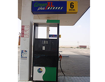
There are basically three stages for a natural gas compressor station: scrubbing, compressing, and cooling. The natural gas compressor station layout is fairly straightforward, as the gas compressor stations process is a continuous flow process. Here is a natural gas compressor station process flow diagram, courtesy of Spectra Energy. This
Gas compressor stations SENER Renewables, Power, Oil & Gas
Gas compressor stations. Gas compressor stations ensure that natural gas maintains sufficient pressure on its journey through long distance pipelines. SENER performs the engineering, construction, and start up of this type of installation through to its turnkey delivery to the client.